MIL-STD-461
EMC Military Test Standard
MIL-STD-461 is a standard issued by the U.S. Department of Defense (DoD) that defines electromagnetic interference control requirements for equipment and subsystems used in military applications. The current revision is MIL-STD-461H, published in April 2026, superseding MIL-STD-461G (2015).Electromagnetic Compatibility Testing
EMC Testing for Military and Defense Equipment
IB-Lenhardt AG and its subsidiary IBL-Lab GmbH provide EMC testing services aligned with MIL-STD-461 requirements for military, defense, and mission-critical electronic equipment.
Our laboratory supports conducted and radiated emission and susceptibility testing to evaluate how equipment behaves in defined electromagnetic environments. This helps manufacturers, system integrators, and project teams identify EMC risks early, prepare technical documentation, and support qualification programs.
We assist with test planning, setup definition, measurements, and documentation for MIL-STD-461 projects, including early-stage development support and project-specific requirement clarification.
MIL-STD-461H
Measurement Classification
In 1967, the U.S. Department of Defense introduced MIL-STD-461 to incorporate electromagnetic compatibility considerations into the development of military communications technology. Since then, several revisions of MIL-STD-461 have been published. The current revision, MIL-STD-461H, was published in April 2026, superseding MIL-STD-461G (2015). Although compliance with MIL-STD-461 is not mandatory for non-military entities, many civilian organizations are also adopting the standard.
MIL-STD-461H describes EMC test requirements and procedures for electronic, electrical, and electromechanical equipment and subsystems, with applicability depending on platform, installation, and procurement requirements.
The MIL-STD-461 test methods are commonly grouped by emission and susceptibility measurements, and by conducted and radiated test setups.
Contact Us
The experts at IB-Lenhardt AG and IBL-Lab GmbH can support you with project-specific questions on MIL-STD-461 testing.MIL-STD-461 Testing Lab
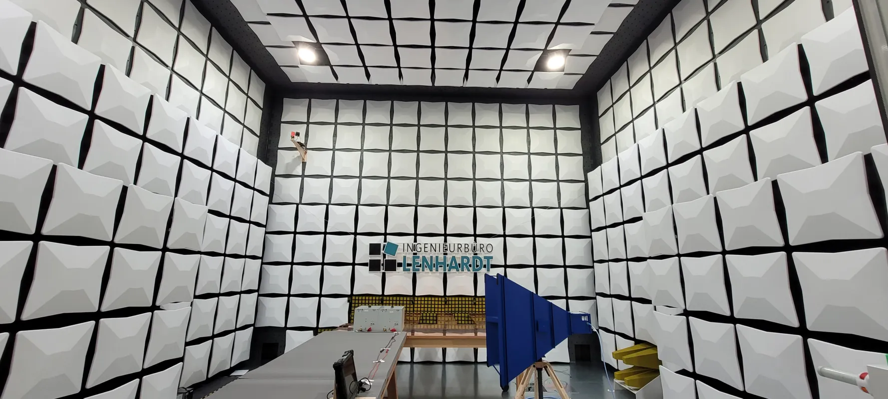
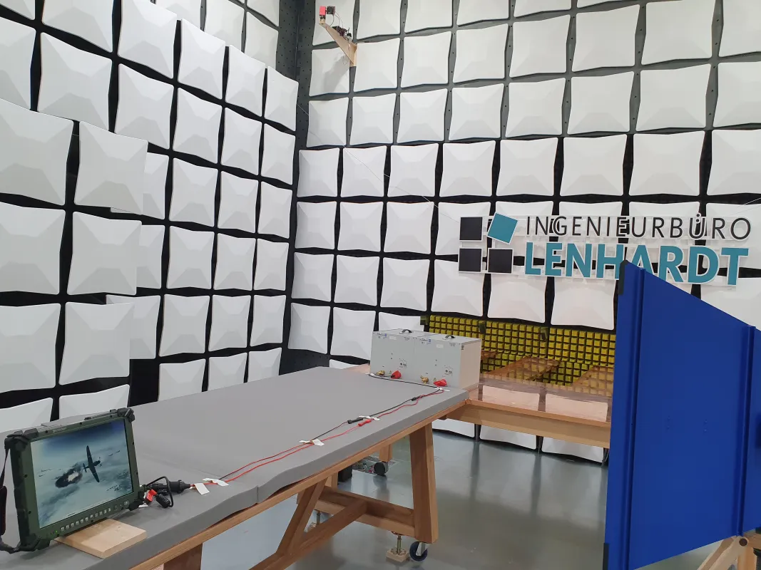
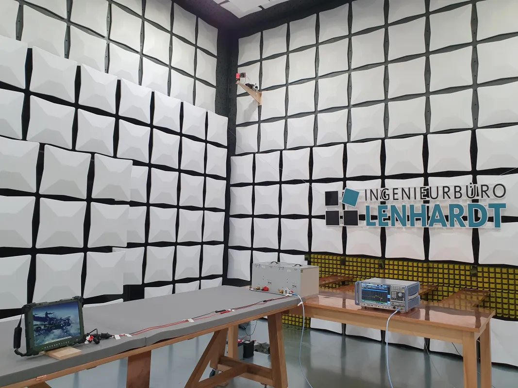
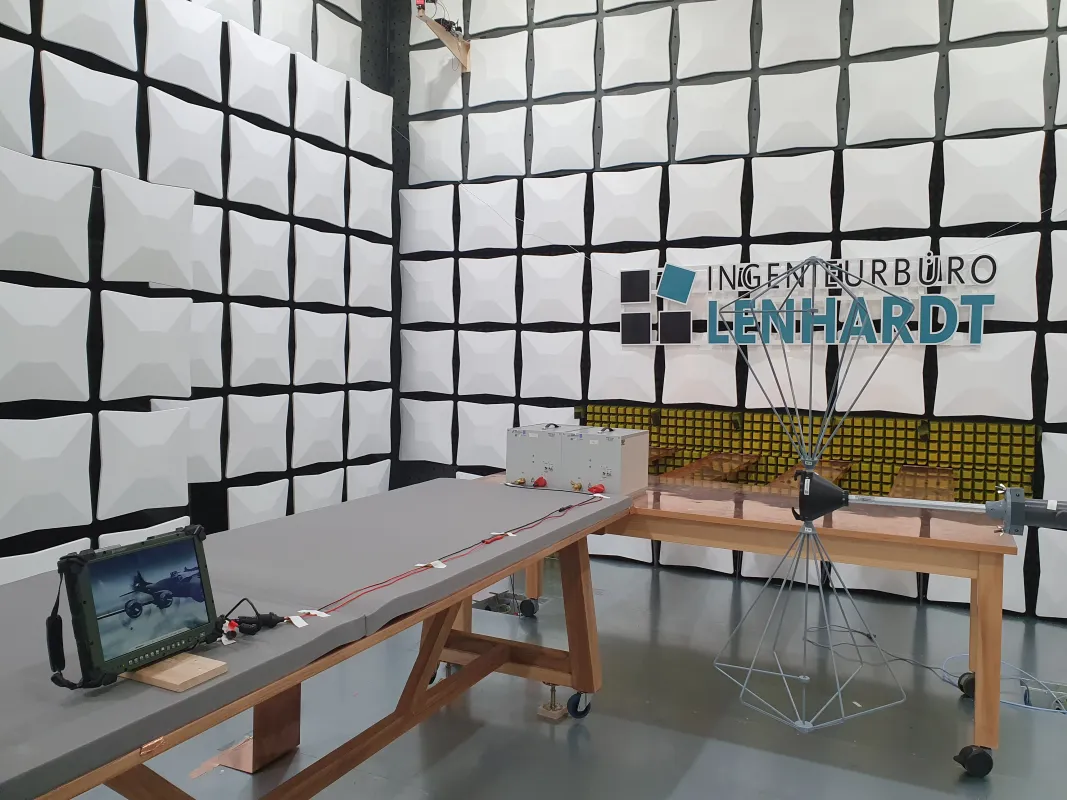
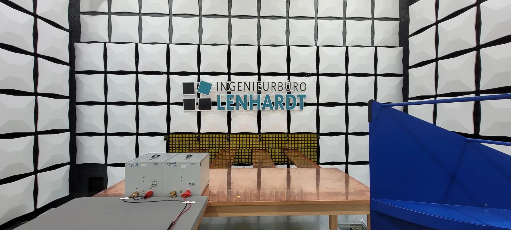
Explore insights into our EMC testing facility. Our lab is equipped for advanced testing, including setups for CE101 (Conducted Emissions) and RE102 (Radiated Emissions). Gain a closer look at our processes and ensure compliance with military standards.
Main Changes in MIL-STD-461H
Key Updates Compared with Revision G
CE101 — Applicability extended from 10 kHz to 20 kHz for surface ships and submarines. Aircraft applications remain capped at 10 kHz, including Army aircraft and Navy aircraft with ASW equipment.
Emission measurement scanning — Synthesized or step-tuned measurement receivers must now step in one-quarter bandwidth increments or less (previously one-half), roughly doubling the minimum number of measurement points per scan. Table II also no longer includes the analog-tuned measurement receiver column.
Overload precautions — Checks must now be performed and documented for each measurement setup (previously specified as periodic checks).
Cable construction §4.3.8.6 — Restructured into three distinct subsections separating construction of input power leads, construction of interconnecting cables, and arrangement of EUT cables.
CS101 — Test equipment options expanded with differential probe and ripple detection transducer as alternatives to the previous isolation-transformer approach for oscilloscope-based measurements.
RE101 — New procedural notes on frequency spectrum subdivision for adequate resolution and per-signal test location selection.
RE102 — Antenna boresight orientation now explicitly defined: front surface parallel to EUT test boundary, elevation parallel to floor, and azimuth perpendicular to setup boundary.
Knowledge Base
Technical Reference
For a detailed comparison, see our Knowledge Base overview of verified MIL-STD-461G-to-H changes and their impact on EMC test planning, setup, CE101 applicability, and documentation.
Applicability
MIL-STD-461H applies to subsystems and equipment for:
Applicability
The MIL-STD-461H Standard is applicable for subsystems and equipment of:
Test Procedures
Equipment and Subsystems
| Equipment and subsystems installed in, on or launched from the following platforms or facilities: | Requirement Applicability | ||||||||||||||||||
|---|---|---|---|---|---|---|---|---|---|---|---|---|---|---|---|---|---|---|---|
| CE101 | CE102 | CE106 | CS101 | CS103 | CS104 | CS105 | CS109 | CS114 | CS115 | CS116 | CS117 | CS118 | RE101 | RE102 | RE103 | RS101 | RS103 | RS105 | |
| Surface Ships | A | A | L | A | S | S | S | L | A | S | A | L | S | A | A | L | L | A | L |
| Submarines | A | A | L | A | S | S | S | L | A | S | A | S | S | A | A | L | L | A | L |
| Aircraft, Army, Including Flight Line | A | A | L | A | S | S | S | S | A | A | A | L | A | A | A | L | A | A | L |
| Aircraft, Navy | L | A | L | A | S | S | S | S | A | A | A | L | A | L | A | L | L | A | L |
| Aircraft, Air Force | S | A | L | A | S | S | S | S | A | A | A | L | A | S | A | L | S | A | S |
| Space Systems, Including Launch Vehicles | S | A | L | A | S | S | S | S | A | A | A | L | S | S | A | L | S | A | S |
| Ground, Army | S | A | L | A | S | S | S | S | A | A | A | S | A | S | A | L | L | A | S |
| Ground, Navy | S | A | L | A | S | S | S | S | A | A | A | S | A | S | A | L | L | A | L |
| Ground, Air Force | S | A | L | A | S | S | S | S | A | A | A | S | A | S | A | L | S | A | S |
A: Applicable. L: Limited as specified in the individual sections of this standard. S: Procuring activity must specify in procurement documentation.
Source: MIL-STD-461H, Table V. © IB-Lenhardt AG 2026
Test Methods
Emission and Susceptibility
Conducted and radiated Emission
| CE101 | Power Leads, 30 Hz to 20 kHz* |
|---|---|
| CE102 | Power Leads, 10 kHz to 10 MHz |
| CE106 | Antenna Terminal, 10 kHz to 40 GHz |
| RE101 | Magnetic Field, 30 Hz to 100 kHz |
| RE102 | Electric Field, 10 kHz to 18 GHz |
| RE103 | Antenna spurious and harmonic outputs, 10 kHz to 40 GHz |
Conducted and radiated Susceptibility
| CS101 | Power Leads, 30 Hz to 150 kHz |
|---|---|
| CS103 | Antenna Port, Intermodulation, 15 kHz to 10 GHz |
| CS104 | Antenna Port, Rejection of Undesired Signals, 30 Hz to 20 GHz |
| CS105 | Antenna Port, Cross-Modulation, 30 Hz to 20 GHz |
| CS109 | Structure Current, 60 Hz to 100 kHz |
| CS114 | Bulk Cable Injection (BCI), 10 kHz to 200 MHz |
| CS115 | Bulk Cable Injection (BCI), Impulse Excitation |
| CS116 | Damped Sinusoidal Transients, Cables and Power Leads |
| CS117 | Lightning Induced Transients |
| CS118 | Personnel Borne Electrostatic Discharge |
| RS101 | Magnetic Field, 30 Hz to 100 kHz |
| RS103 | Electric Field, 2 MHz to 40 GHz |
| RS105 | Transient Electromagnetic Field |
| Subtest | Scope | Subtest | Scope |
|---|---|---|---|
| Conducted and radiated Emission | |||
| CE101 | Power Leads, 30 Hz to 20 kHz* | RE101 | Magnetic Field, 30 Hz to 100 kHz |
| CE102 | Power Leads, 10 kHz to 10 MHz | RE102 | Electric Field, 10 kHz to 18 GHz |
| CE106 | Antenna Terminal, 10 kHz to 40 GHz | RE103 | Antenna spurious and harmonic outputs, 10 kHz to 40 GHz |
| Conducted and radiated Susceptibility | |||
| CS101 | Power Leads, 30 Hz to 150 kHz | CS116 | Damped Sinusoidal Transients, Cables and Power Leads |
| CS103 | Antenna Port, Intermodulation, 15 kHz to 10 GHz | CS117 | Lightning Induced Transients |
| CS104 | Antenna Port, Rejection of Undesired Signals, 30 Hz to 20 GHz | CS118 | Personnel Borne Electrostatic Discharge |
| CS105 | Antenna Port, Cross-Modulation, 30 Hz to 20 GHz | RS101 | Magnetic Field, 30 Hz to 100 kHz |
| CS109 | Structure Current, 60 Hz to 100 kHz | RS103 | Electric Field, 2 MHz to 40 GHz |
| CS114 | Bulk Cable Injection (BCI), 10 kHz to 200 MHz | RS105 | Transient Electromagnetic Field |
| CS115 | Bulk Cable Injection (BCI), Impulse Excitation |
* Aircraft applications remain limited to 10 kHz as specified in MIL-STD-461H.
Contact us
MIL-STD-461 Testing
Have questions about the testing scope? Contact us to discuss your MIL-STD-461 requirements, test setup, and project-specific documentation needs.
General Requirements
Measurement Setup
- Calibration
-
Measurement devices should be calibrated according to ANSI/ISO/IEC 17025 or ISO 10012. Passive devices, such as antennas, clamps, and probes, require initial calibration.
- Test environment
-
Measurements are preferably performed in anechoic rooms.
- Tolerances
-
Distance: ±5%
Frequency: ±2%
Amplitude, measurement receiver: ±2 dB
Amplitude, measurement system (includes measurement receivers, transducers, cables, and so forth): ±3 dB
Time (waveforms): ±5%
Resistors: ±5%
Capacitors: ±20%
- Environmental noise
-
For CE101 and CE102, ambient levels should be at least 6 dB below the applicable limit. Where required, the EUT may be replaced by a resistive load to verify the ambient level.
- Ground plane
-
The EUT shall be installed on a ground plane that simulates the actual installation. If the actual installation is unknown or multiple installations are expected, then a metallic ground plane shall be used.
- Metallic ground plane
-
Size: > 2.25 m²
Depth: > 76 cm
Resistance: < 0.1 mΩ/square
Bonding Distance between ground connectors: < 1 m
Format: < 5:1
Material: Solid
Ground resistance: < 2.5 mΩ
Instrumentation Setup
MIL-STD-461H Table II: Bandwidth and Dwell Time
| 30 Hz – 1 kHz | 6 dB BW: 10 Hz Step-Tuned: 0.15 s FFT: 1 s/BW |
|---|---|
| 1 kHz – 10 kHz | 6 dB BW: 100 Hz Step-Tuned: 0.015 s FFT: 1 s/BW |
| 10 kHz – 150 kHz | 6 dB BW: 1 kHz Step-Tuned: 0.015 s FFT: 1 s/BW |
| 150 kHz – 10 MHz | 6 dB BW: 10 kHz Step-Tuned: 0.015 s FFT: 1 s/BW |
| 10 MHz – 30 MHz | 6 dB BW: 10 kHz Step-Tuned: 0.015 s FFT: 0.15 s/BW |
| 30 MHz – 1 GHz | 6 dB BW: 100 kHz Step-Tuned: 0.015 s FFT: 0.15 s/BW |
| Above 1 GHz | 6 dB BW: 1 MHz Step-Tuned: 0.015 s FFT: 0.015 s/BW |
| Frequency Range | 6 dB Resolution Bandwidth | Minimum Dwell Time | |
|---|---|---|---|
| Step-Tuned Receiver | FFT Receiver | ||
| 30 Hz – 1 kHz | 10 Hz | 0.15 s | 1 s/BW |
| 1 kHz – 10 kHz | 100 Hz | 0.015 s | 1 s/BW |
| 10 kHz – 150 kHz | 1 kHz | 0.015 s | 1 s/BW |
| 150 kHz – 10 MHz | 10 kHz | 0.015 s | 1 s/BW |
| 10 MHz – 30 MHz | 10 kHz | 0.015 s | 0.15 s/BW |
| 30 MHz – 1 GHz | 100 kHz | 0.015 s | 0.15 s/BW |
| Above 1 GHz | 1 MHz | 0.015 s | 0.015 s/BW |
MIL-STD-461H no longer specifies minimum measurement times for analog-tuned receivers, as analog measurement equipment is considered obsolete. Table II now covers step-tuned and FFT receiver configurations only.
Related Test Methods
European and International Military Standards
DEF-STAN 59-41
DEF-STAN 59-411
MIL-STD-462
MIL-STD-464
MIL-STD-704
MIL-STD-810
MIL-STD-1275
NATO: AECTP 250
NATO: AECTP 500
RTCA: RTCA/DO-160
Testing Services for Military Electronics and Radar Systems
EMC and RF testing for military and defense applications, including test setups aligned with MIL-STD-461, NATO AECTP-500, VG 95370, and VG 95373
DAkkS-accredited testing capabilities using anechoic and semi-anechoic chambers, copper shielded rooms, and defined ground plane setups
EMC test engineers with experience in MIL-STD-461 test planning, setup definition, measurement, and reporting
Testing and documentation support for defense standard validation and equipment qualification programs
Project-specific consulting for test scope definition, qualification planning, schedule coordination, and component verification
Our engineers support testing, documentation, and project-specific clarification throughout the MIL-STD-461 test process.